Determine the Resistivity of a Wire Using a Metre Bridge – Class 12 Practical
- June 10, 2019
Aim
To determine the resistivity (specific resistance) of a given wire by using a metre bridge (Wheatstone bridge) to measure the resistance of a known length of wire and calculating resistivity from measured diameter and length.
Apparatus Required
Metre bridge, a test wire of known length, low-value resistance box, galvanometer and jockey, one-way key, cell or battery eliminator, thick connecting wires, sand paper, and screw gauge.
Theory
To find the resistance of the wire
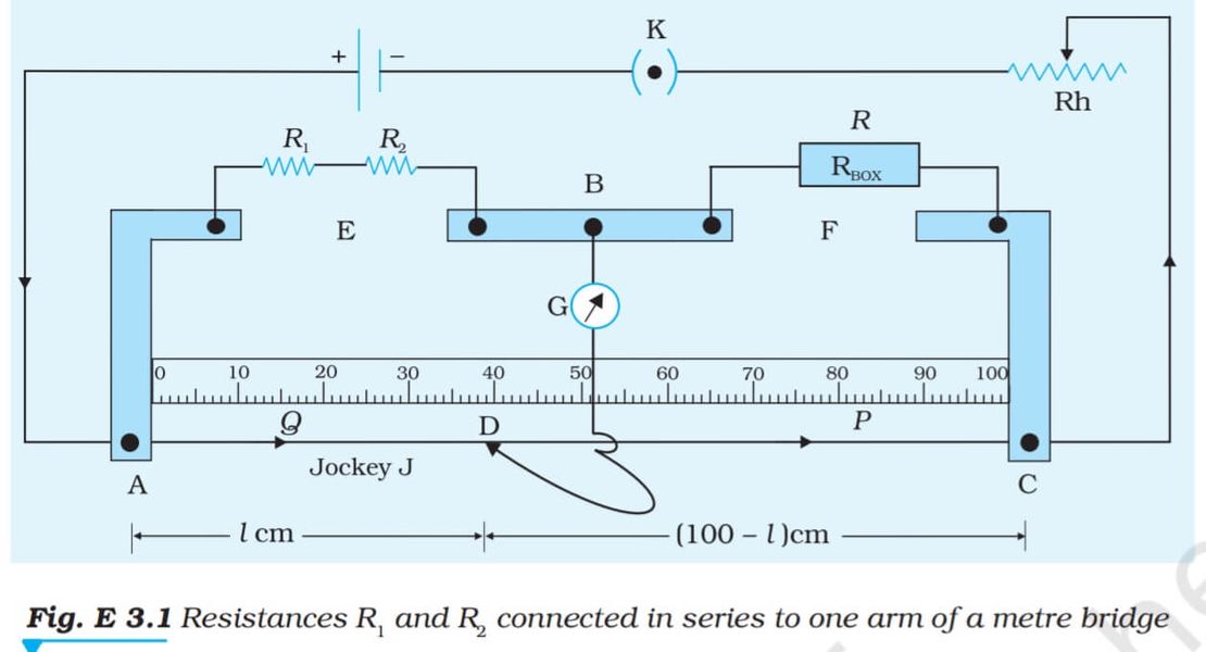
A metre bridge works on the principle of the Wheatstone bridge.
The unknown resistance X is placed in the right gap, while a known resistance R from the resistance box is in the left gap.
When the bridge is balanced (null deflection on galvanometer):
[ \frac{P}{Q} = \frac{L}{100 - L} ]
[ \frac{P}{Q} = \frac{R}{X} ]
[ X = \frac{R(100 - L)}{L} ]

Specific Resistance (Resistivity)
The resistivity ( \rho ) of the wire is:
[ \rho = \frac{RA}{L} = \frac{\pi r^2 X}{L} ]
where
• r = radius of wire
• L = length of wire
• X = resistance of wire
Procedure
- Measure the diameter of the wire using a screw gauge and calculate its radius.
- Clean insulation from connecting wires using sand paper. Press all resistance box plugs tightly.
- Set up the circuit as shown, with the unknown resistance in one gap.
- Introduce resistance R from the resistance box.
Touch the jockey first at A and then at C.
Observe the galvanometer deflection direction.
Ensure the jockey touches the wire only for a fraction of a second. - Adjust R so that the null point lies between 30 cm and 70 cm.
- Repeat step 4 for four different values of R.
- Interchange resistances S and R and repeat the same procedure.
Ensure the same length of wire is in the gap after interchange.


Precautions
- Ensure all connections are tight and wires are cleaned before connecting.
- The jockey should not be pressed hard and must slide gently.
- Balance point should lie near the midpoint of the wire.
- Percentage error should be kept minimal.
Sources of Error
- Non-uniform thickness of the wire.
- Loose resistance box plugs.
- Heating of wires due to continuous current.
- Contact resistance due to improper connections.