Verify Series and Parallel Laws of Resistance Using a Metre Bridge
- June 11, 2019
Aim
To verify the laws of combination of resistances (series and parallel) using a metre bridge.
Material Required
- Metre bridge
- Sensitive galvanometer
- Two different resistances (carbon or wire-wound)
- Resistance box
- Jockey
- Rheostat
- Plug key
- Cell or battery eliminator
- Thick connecting wires
- Sand-paper
Theory
- Series Combination: If resistances ( R_1 ) and ( R_2 ) are in series, the total ( R_s = R_1 + R_2 )
- Parallel Combination: If in parallel,
[ \frac{1}{R_p} = \frac{1}{R_1} + \frac{1}{R_2} ]
Circuit Diagrams
Series Circuit:
Parallel Circuit:
Procedure
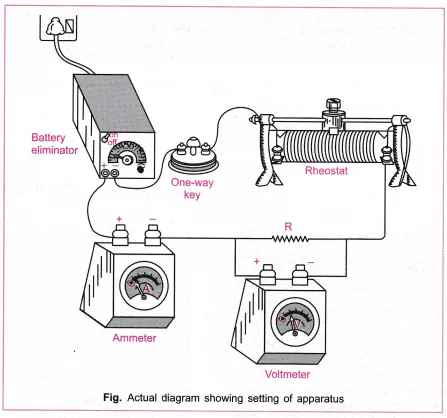
- Setup: Make all connections neatly. Tighten all plugs of resistance box. Clean wire ends with sandpaper.
- Series Method:
- Insert plugs to get a suitable resistance ( R ) from the box.
- Slide jockey along the metre bridge wire to find the null point D (zero deflection of galvanometer).
- Measure lengths ( AD ) and ( DC ) in the metre bridge wire.
- Record ( R, AD, DC ).
- Repeat for at least 5 different values of ( R ), compute the series-equivalent resistance ( X ).
- Parallel Method:
- Reconfigure the resistors ( R_1, R_2 ) in parallel, rewire the bridge.
- Repeat steps to find null point and corresponding lengths.
- Calculate parallel-equivalent resistance ( X ) for parallel combination.
Observations & Calculations

Precautions
- Ensure all connections and resistance box plugs are tight.
- Move the jockey gently on the metre-bridge wire.
- Tighten plug keys in the resistance box properly (clockwise).
- Try to get null point in the central region of the bridge wire (30 cm to 70 cm).
Sources of Error
- Wire thickness may not be uniform.
- Plugs in the resistance box may not be fully tight.
- Wire may heat up due to continuous current, changing resistance.
- Contact resistance from bad connections can affect readings.